Topology Characterization for Position-based Wireless Network Topology Generators

Computer networks are usually characterized by their graph properties. Thus, a network consists of vertices representing network nodes and directed or undirected edges representing connectivity. Such networks can be characterized by density, average degree, diameter, and clustering coefficient. These measures have been successfully applied to describe mostly static, wirebound networks, such as generated random networks with Internet-like characteristics.

However, wireless network simulations typically compute a network by first using a spatial model to place the nodes, followed by calculating the connection probability with a radio propagation model.
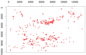
The node positions of the Berlin Freifunk wireless mesh network clearly indicated a non-uniform distribution

The connectivity of two nodes depends on the signal to noise ratio at the receiving node, which is a function of path loss, shadowing and fading models, and the current transmission power of nearby nodes. Connectivity models often are probabilistic, thus yielding an expected reception probability for any given link.

To characterize wireless networks, we suggest an alternative approach to using graph-theoretical network properties alone. We propose four metrics for this use case – nearest neighbor distribution, threshold degree, probabilistic degree, and inhomogeneity factor – and demonstrated their application using four real-world networks and an artificially created topology as examples. Our examples show that real-world topologies are much more spatially clustered than a uniform distribution of nodes on the same terrain would be. The nearest neighbor metric and inhomogeneity factor can be used to directly assess the amount of clustering in such topologies while the threshold and probabilistic degree will give an indication of what to expect in terms of the resulting graph once the propagation model is applied. Consequently, we recommend employing all four metrics in order to describe a topology with respect to its network properties and assess its validity for use in simulation.

To learn more, check out the paper:

Martina Umlauft and Wilfried Elmenreich. Topology Characterization for Position-based Wireless Network Topology Generators. In Anna Maria Vegni, editor, 15th International Conference on Wireless and Mobile Computing, Networking and Communications (WiMob 2019), Piscataway (NJ), Oktober 2019. IEEE.

Posted in Simulation, Wireless Networks | Leave a comment

Three PhD Positions on Technical Sciences at Alpen-Adria-Universität Klagenfurt

The Institute of Networked and Embedded Systems at the University of Klagenfurt, Austria, has three openings for researchers (PhD student) on the topics of
– software engineering of swarm systems
– system testing and fault diagnosis
– embedded communication protocols.

Candidates are expected to have a master in electrical or computer engineering, computer science, applied mathematics or equivalent. Experience (by study or work experience) in two or more of the following fields is required:

– Distributed and swarm algorithms
– Simulation or Multi-Agent Systems
– Circuit design and simulation
– Embedded communication protocols
– Excellent programming skills in Java, C# or Python

You will work at the Smart Grids group at the Institute of Networked and Embedded Systems under the supervision of Professor Wilfried Elmenreich. The institute cooperates with national and international partners from industry and academia and is part of the research cluster Lakeside Labs (self-organizing networked systems).

Our team is very international and dedicated to quality research and teaching. Our working language is english. The offices and laboratories are located in the well-equipped Lakeside Science & Technology Park. The Institute cooperates with national and international partners in research and industry. It is part of the research cluster Lakeside Labs on self-organizing networked systems. The PhD will be embedded within research projects in collaboration with local companies and will enable the candidate to gain also professional experience.

The contract will be based on a gross salary of at least 39124 EUR per year for 40 hours per week. Please mail applications containing a letter of interest, curriculum vitae, copies of academic certificates and courses, list of publications, a PDF of your master thesis and contact details of two references in a single PDF file to wilfried.elmenreich@aau.at . Women are especially encouraged to apply.

Deadlines for applications:
1st round: 25.09.2018
2nd round: 31.10.2018

Posted in Embedded Software, Hardware, Protocols, Real-Time Networks, Self-Organizing Systems, Simulation | Tagged , , , | Leave a comment

Integrating Time-Triggered and Event-Triggered Communication in a Hard Real-Time System

The setup and verification of time-triggered communication systems are very tedious. Detailed process time information like the Worst Case Execution Time (WCET) must be gathered beforehand to determine the slot sizes such that no slot violations occur. For highly dynamical systems like prototypes, the investigation of the WCETs and thus the setup is very costly. Here, mostly the code is modified which influences the process execution time.

In this paper, we present two mechanisms, which provide additional information about the time-triggered bus communication state during run-time. The gathered information is used to identify tight slot boundaries which simplifies the setup and verification of such a system.

Scenarios

Fallback communication scenarios

As a prerequisite, we assume that the predefined schedule is imprecise due to missing process time information. Therefore, our first mechanism is applied to detect slot violations. At the beginning of each slot, the participants check if the previous message already arrived. If this is not the case, a slot violation occurred and the current task’s execution is delayed until the expected message is received. With this, message collisions are prevented and the entire communication system is kept alive.

Rating

Slot rating using three different quality regions

The second mechanism is applied to gather detailed information during run-time which is used to rate various slot specific qualities. Thereby, the bus communication is analyzed by tracking the message reception times. The gathered data is compared to the known slot boundaries and the quality ratings are determined. As a result, the additional information enables an implicit verification of the communication state which can further be used for an extended node control.

We claim, that the gathered information will reduce the effort to set up and verify a time-triggered bus communication in highly flexible systems. The feasibility and performance of the presented mechanisms are currently investigated and will be presented in a follow-up paper.

S. Einspieler, B. Steinwender, W. Elmenreich. Integrating Time-Triggered and Event-Triggered Communication in a Hard Real-Time System. In Proceedings of the 1st IEEE International Conference on Industrial Cyber-Physical Systems (ICPS 2018), St. Petersburg, Russia, May 2018.

Posted in Real-Time Networks | Leave a comment

Applying Kapton Foil Without Bubbles – The Wet Method

Kapton is a polyimide film wich can withstand a wide range of possible temperatures from -269°C to 350°C. Therefore, it is an optimal material to cover the printing bed of a 3D printer. You might have seen the thin yellow foil on some 3D printing beds before. Kapton can be bought as a tape or foil, both come with a sticky side, ready to be put onto the glass surface of your printers pad. However, when applying the Kapton tape or foil to a glas surface, you often end up with bubbles – at least it happens to me. Since the sticky sides sticks very well, it is almost impossible to get rid of the bubbles, which defies the purpose of having a nice smooth surface for your prints.

The best way to apply a Kapton foil without bubbles is the “Wet method”. By applying a thin layer of detergent and water onto the glass surface, the Kapton tape sticks a bit less in the beginning, which allows you to remove any bubbles that may form on the adhesive side with a ruler. I made a video of showing the overall procedure.

Thanks to Sriram for the camera work! You can spot him at the end of the video.

Posted in Hardware | Tagged | Leave a comment

Programming the Arduino Pro from a PC

I admit, programming the Arduino Pro from a PC is no rocket science, however it is always useful to have a tutorial at hand that shows the steps how it is done. Therefore, I would like to share the experiences we had with programming an Arduino Pro Mini as part of our Swarm Robot “VIPL” [1].

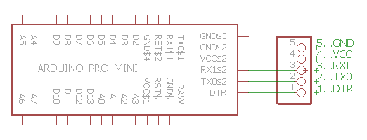
On the printed circuit board we added a connector for serial programming to the Arduino with the following wiring scheme:

programming-connector-arduino

As a programmer, we used a BTE13-007 (the updated version BET13-009 is currently sold for less than 2€).

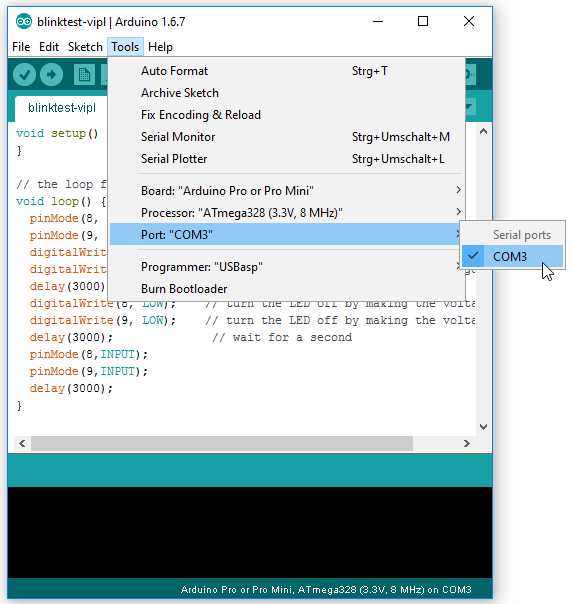
The programmer has a USB connector and maps itself as a COM port. It plays nicely with the Arduino Studio, you just have to set the correct COM-port in the tools settingh of your Arduino Studio:

settings-arduino-studio-english

The picture also shows the other settings for the Arduino type and microcontroller and the programmer type, here “USBasp” works fine for me.

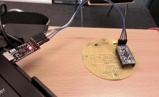
Now its hardware again, we need to connect the programmer with the board. This can be done with a five-wire connector (the CTS of the programmer will not be used) as shown in this photo:

programming-connector

Some search showed there is no consensus how to assign colors to the wires depending on the signal. In this picture we used the following colors:

blue – GND – Pin5 of programming connector (GND)
violet – 5V – Pin4 (VCC)white – TxD – Pin3 (RXI)
gray – RxD – Pin2 (TXO)
black – DTR – Pin1 (DTR)

Feel free to use any other colors, but keep the same connections 😉

That’s it, now we can start to program our Arduino. Note that while it is connected as shown in the picture above it will be powered via USB.

[1] W. Elmenreich, B. Heiden, G. Reiner, and S. Zhevzhyk. A low-cost robot for multi-robot experiments. In Proceedings of the 12th International Workshop on Intelligent Solutions in Embedded Systems (WISES’15), pages 127–132, Ancona, Italy, October 2015. (fulltext)

Posted in Embedded Software, Hardware, Uncategorized | Tagged , , | Leave a comment

ROBOTICS 48h Game Jam in Klagenfurt

ROBOTICS 48h Game Jam
Topic “Rehabilitation Robotics”
November 23-25, 2016
15:30-19:00

organized by
JOANNEUM RESEARCH ROBOTICS, Klagenfurt

Game jam takes place in
Lakeside B07, 9020 Klagenfurt, Klagenfurt

DESCRIPTION

As part of this year’s European Robotics Week, ROBOTICS is hosting a 48h Gam Jam on the premises of the Lakeside Science and Technology Park in Klagenfurt from 23 to 25 November 2016 on “Rehabilitation Robotics – Development of a Serious Game with the Integration of a Robot!”
This is an excellent meeting point for committed students from different disciplines that want to work together on future technologies.

What is a Game Jam?
A game jam is a collaboration of game developers to jointly plan, design and develop a game within a short period of time. In the process, people from different disciplines such as programmers, game designers, artists etc. work together.

THEME
“Rehabilitation Robotics – Development of a Serious Game involving a Robot!”

PARTICIPATION
Limited places, so please register at robotics-office@joanneum.at
The participation is free – food and drinks will be provided!

Posted in Embedded Software, Robotics, Software | Tagged , | Leave a comment

JProwler – A simple Wireless Network Simulator in Java

When I was a visiting researcher at the Institute of Software Integrated Systems at Vanderbuilt University in 2005, I learnt about a Wireless Network Simulator named JProwler. JProwler evolved from a simulator named PROWLER, short for Probabilistc Wireless Network Simulator.

What I liked was the compact format, the whole simulator fits into less than 20 well-structured Java classes, while implementing a simulator with different timing modes, a graphical display and an event-based underlying simulation engine.

For this reason, I still use JProwler in a lecture on network simulation as an example how a simulator could be implemented from scratch. Unfortunately, a student recently told me that the offificial download for JPROWLER is gone, therefore I provide the code, which is under a free software license here for download:

See also this paper from the authors of PROWLER and JPROWLER explaining the concepts:

G. Simon, P. Volgyesi, M. Maroti, and A. Ledeczi, “Simulation-based optimization of communication protocols for large-scale wireless sensors networks,” Proceedings of the IEEE Aerospace Conference 3:1339–1346, March, 2003.

and this work showing what can be done with JPROWLER:

H. Adam, W. Elmenreich, C. Bettstetter, and S. M. Senouci. CoRe-MAC: A MAC-protocol for cooperative relaying in wireless networks. In Proceedings of the 2009 IEEE Global Communication Conference (Globecom), Honolulu, Hawaii, 2009.

Posted in Protocols, Simulation, Wireless Networks | Tagged , , | Leave a comment

Making and Programming 3D-Printed Robots

MakerClub.org is a webpage offering 3D-printable designs and control software for small 3D-printable robots.

By building robots from the Make Club webpage one can learn the skills to design and construct own robots. Definitely worth a visit!

Posted in Hardware, Robotics | Tagged , , , , | Leave a comment

Autonomous Hexbug Spider

Autonomous Hexbug Spider

Autonomous Hexbug Spider

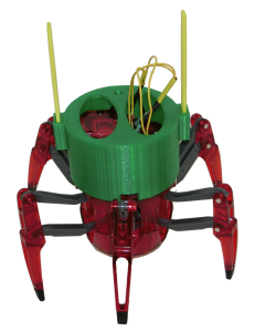
The  Hexbug Spider XL is an interesting toy – originally it comes as cheap remote-controlled robot, but at the same time it can be viewed as a cost efficient chassis to build an autonomous robot. There are two motors inside of this spider: one of them controls six-legged crawling motion and the second motor allows to rotate its head on 360 degrees. 3 AA-bateries set internal mechanisms in motion. A two-channel RC remote is used to control this fascinating creature. Our intern – Nadja Hölzl – hacked this robot by adding an Arduino Uno for local control of the actuators. As sensors for detecting obstacles we added small-range proximity sensors.  Some parts of modified robot were created using 3D printer. The application of this approach helped us to fix all necessary components on the top of the robot during prototyping phase and refine its visual representation.

Spider head with installed yellow bars on it

Spider head with installed yellow bars on it

An autonomous robot requires both: actuators and sensors. Actuators are responsible for moving and sensors help to measure a physical quantities. Without actuators a robot cannot perform any practical task.  If your robot doesn’t have sensors, then it’s blind. In our case, actuators  are two motors for moving of the spider. Proximity  sensors help to perceive distance to obstacles.

Our hack starts from disassembling – the head of the spider should be removed in order to get access to the motors. To fix all necessary components on the spider, we selected leveling architecture. It allows to add, change or remove parts of the robot without much effort. In general this approach is good for prototyping, but is not optimal in terms of space requirements and used plastic.

3D printed section for battery and proximity sensors

3D printed section for battery and proximity sensors

First, we designed new head for the robot, which is the base for all next layers. There are two oval holes for wires on the top of this model. From two sides of the head you can see the sockets for the bars, which are used to fix other layers.

A 9V battery is used to power all electronic components of the spider. The holder for battery contains sockets where you can attach up to 10 proximity sensors. TCRT5000 is the reflective optical sensor which we use in our experiments to measure a distance to obstacles. Due to distinguishing shape of the spider, we designed a special bar to hold these proximity sensors.

3D printed holder for Arduino board and motor shield

3D printed holder for Arduino board and motor shield

Unfortunately, current from Arduino board is not sufficient to run the motors.   Therefore we used an  Arduino motor shield to control two motors of the robot. Using this shield you can easily connect and operate the two motors.

We used Blender, which is free and open source 3D animation suite, to model all parts of the modification for Hexbug Spider. 3D printer Makerbot Replicator 5G  turned the virtual designs into real physical objects.

And finally you can relax and watch how this graceful creature explores its environment.

All 3D models are freely available on Thingiverse, so you can download them, possibly modify and print on a 3D printer.

Posted in Robotics | Tagged , , , , | Leave a comment

3D Modeling and Printing

3D modeling and printing can be easy if you have the right tools and programs. My experiences with the free Sketch Up Make and the Makerbot Replicator 5G printer are quite positive.

Getting started with 3D modeling:

Download and install Sketch Up Make (if want the program in a language other than english be sure to visit the webpage in the corresponding language) For example, http://www.sketchup.com/de leads to the German version.

Download and install the software for your 3D printer (in my case, the Makerbot desktop).

sketchup-gears-470px

Sketch Up Make model of a gear from a Hexbug spider robot. Gears have been drawn with the Involute Gear plugin.

Start Sketch Up make. If you get an annoying prompt every few minutes, start sketch up make with administrator rights until the demo time for the Pro version is over.

Usually, 3D models are printed from an STL file, so you need to install the STL export extension. The extension can be found and installed via the extension warehouse. The extension warehouse can be found via the Window menu of Sketch Up. For accessing the warehouse extensions, you need to log in with a Google account.

modelrepair

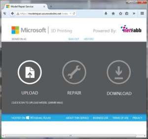
Some models are kind of a fixer/upper: Netfabb/Microsoft’s model repair service

So far you can draw and export STL files.However, these files often suffer from model errors like inverted surfaces, holes, etc. In order to repair these problems, we recommend to run the STL file through the model repair service from NetFabb. The service is free for non-commercial use, but requires to sign in with a MSN ID to be used. Upload your STL there and download a repaired version (unfortunately there is no feedback what has been repaired).

Finally, open the STL with 3D printer software and hit print! Happy printing…

… and waiting hours for the printer to finish.

Posted in Hardware, Tools | Tagged , , | Leave a comment